Circuit Diagram
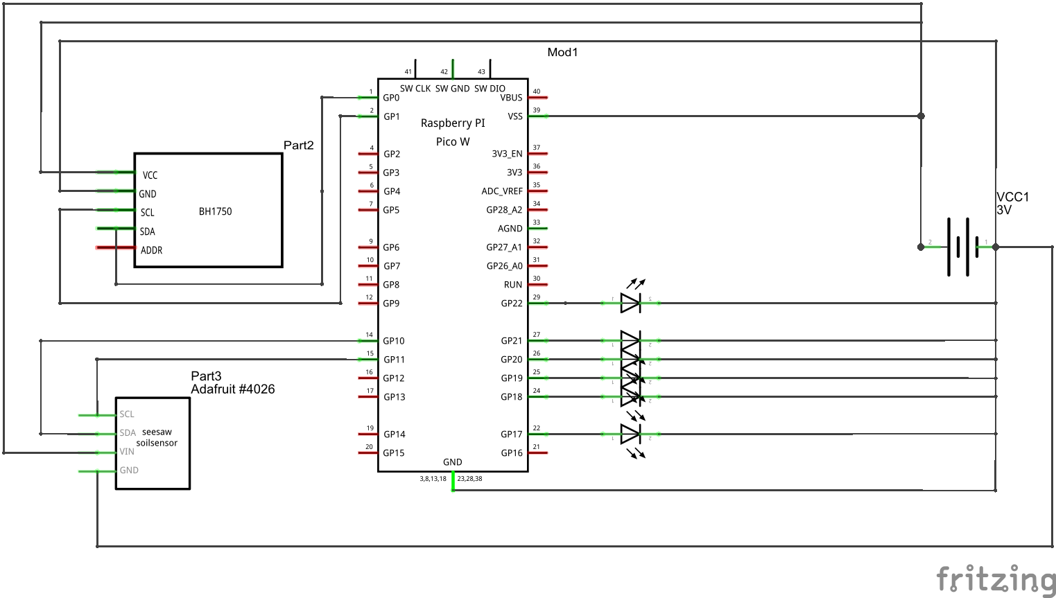
Parts included
- Lipo 3V Battery
- Raspberry Pico W
- BH1750
- Seesaw Soil Sensor
Connections Descriptions
The above diagram depicts the following connections
(1) Lipo3V Battery
- (+) Connections
- Raspberry Pico W VSS Pin 39
- BH1750 VCC Pin
- Seesaw Soil Sensor VIN Pin
- (-) Connections
- Raspberrry Pico W GND Pin
- BH 1750 GND Pin
- Seesaw Soil Sensor GND Pin
- (6) LED Negative connections
(2) Raspbery PI Pico W
- Pin 1 GP0 to BH1750 SCL Pin
- Pin 2 GP1 to BH1750 SDA Pin
- Pin 14 GP10 to Seesaw Soil Sensor SDA Pin
- Pin 15 GP11 to Seesaw Soil Sensor SCL Pin
- GND Pin to Lipo 3V Battery (-) Connection
- Pin 39 VSS Pin to Lipo 3V Battery (+) Connection
- Pin GP17 through Pin GP 22 to LED (+) Side
    - Pin GP17 through Pin GP19 are connected to Red LED
    - Pin GP20 through Pin GP22 are connected to Green LED.
Description
The above diagram is to be used to help facilitate how you can connect the pins to the Raspberry Pico W to the sensors used for the Garden Sensor Array. NOTE : The LEDs have to be connected to the correct pins order when differentiating between Greed and Red